This is the first in a series of articles about the STM32 family of ARM Cortex microcontrollers.
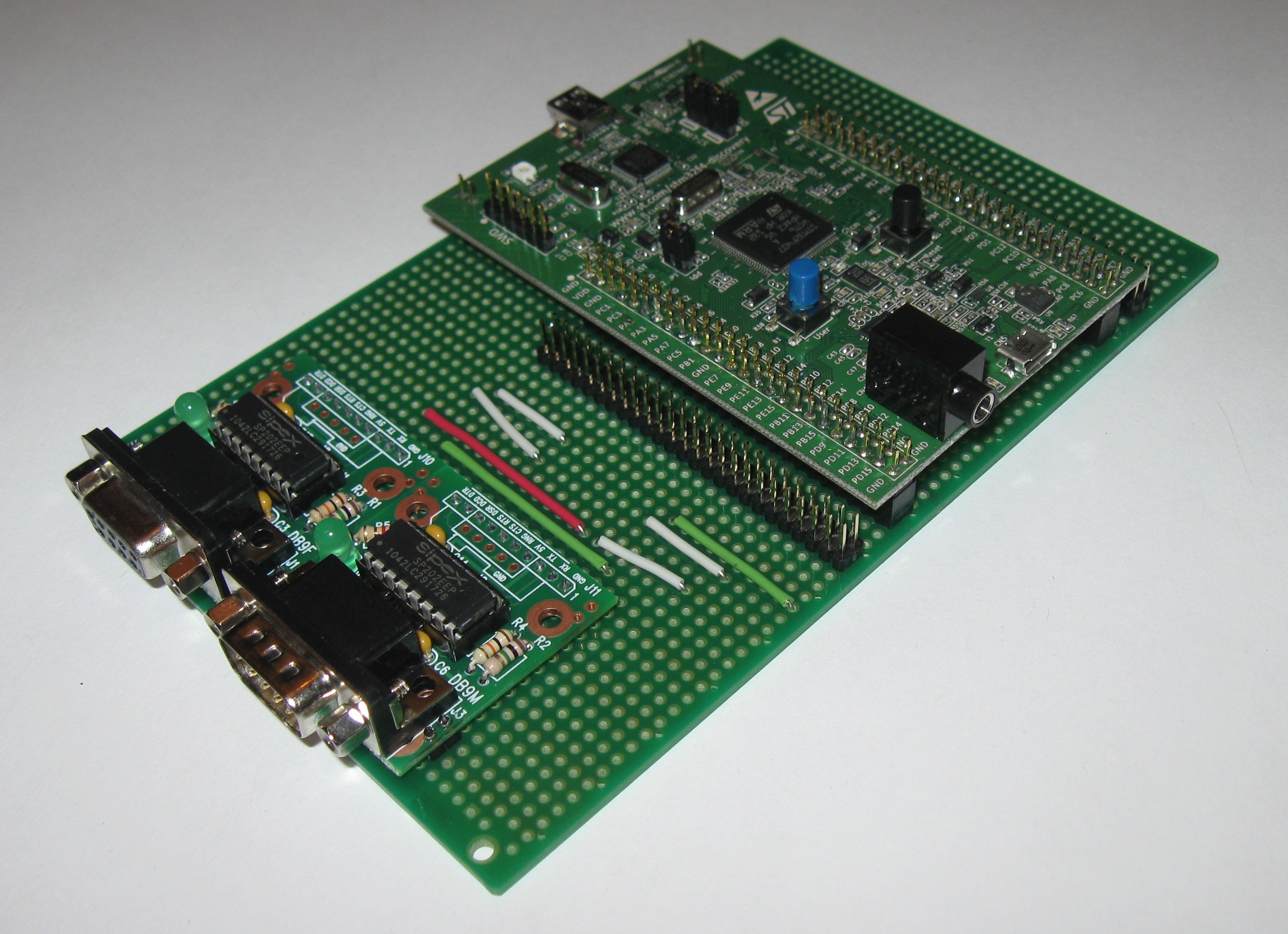 In this article I will show the breakout board I built for the STM32F4 Discovery module. It features two male DIL headers to easily attach jumper wires and two RS232 serial ports
It uses a BusBoard-3U prototyping board to connect the DIL male headers to the Discovery module. For RS232 interfaces I used ComBoard CB232F and CB232M modules to simplify wiring.
The STM32F4-Discovery Module
This fall STMicro gave away thousands of STM32F4 Discovery modules to promote their new ARM Cortex-M4 processor with floating point unit and DSP instructions. You can read about other STM32F4 key features in the STM32F4 press release.
The STM32F4 Discovery module has many great features and it sells for only $18. It has a large memory size that makes this module very useful. The Discovery-F4 module has 1 Megabyte of Flash, which allows large programs to be written. It also has 192k of SRAM, which is huge for a microcontroller. RAM hungry firmware modules, such as file systems and TCP/IP stacks, are much more easily supported with lots of RAM.
Another great feature of the Discovery-F4 is that is has a built in SWD interface, which is the low-cost serial version of a JTAG debug interface. It provides the ability to program the MCU, and set breakpoints, inspect memory, or single-step through your program, which are a great help during debugging. It is a fantastic bargain to get these features in a low-cost development module. The F4’s predecessor modules, the Discovery-VL and Discovery-L, also provide the on-board SWD debug interface.
The STMicro support page for the Discovery-F4 module describes other features of the Discovery-F4 module and provides links to the firmware libraries.
Breakout Headers
The Discovery-F4 module has two 50-pin DIL (dual in-line) headers, called P1 and P2, to connect to the processor pins. You could turn the module upside down and connect directly from the pins to a breadboard with male-female jumper wires. I wanted to make my connectors more permanent with soldered connections for the serial port modules.
The Discovery-F4 module has two 50-pin DIL (dual in-line) headers, called P1 and P2, to connect to the processor pins. You could turn the module upside down and connect directly from the pins to a breadboard with male-female jumper wires. I wanted to make my connectors more permanent with soldered connections for the serial port modules.
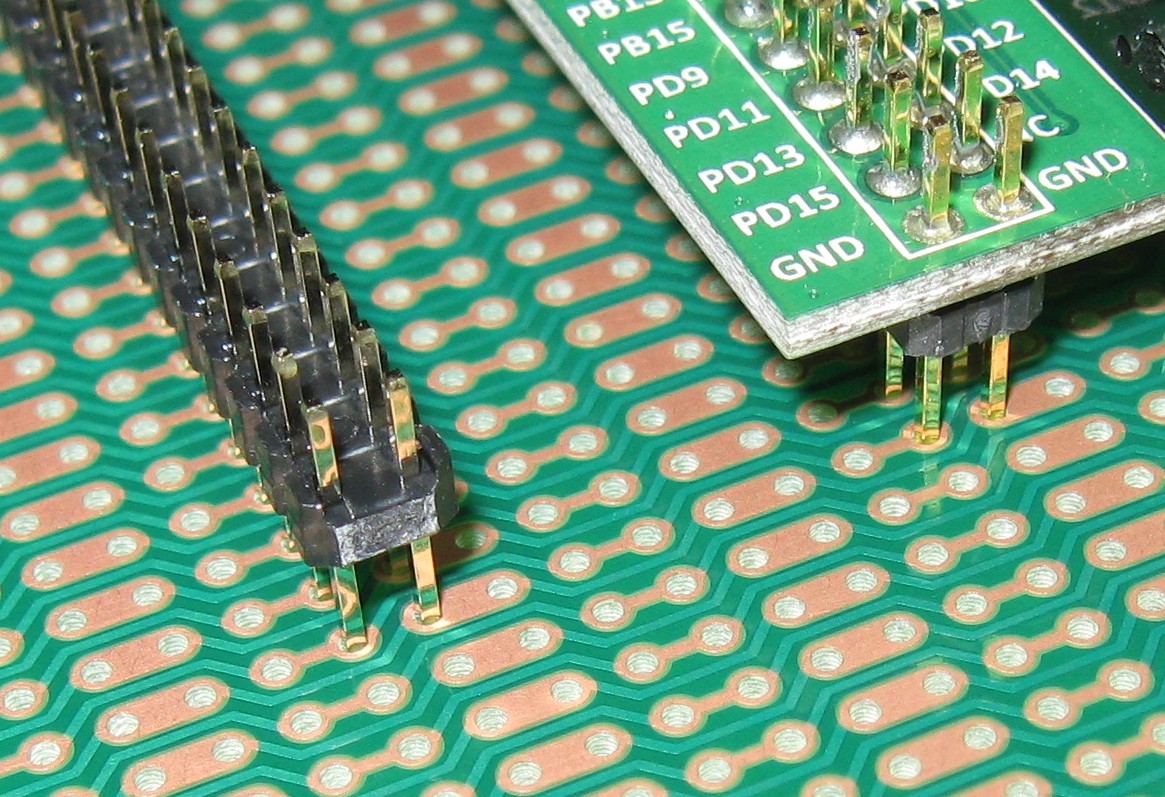
The Discovery-F4 bottom male headers have long tails that protrude from the upper side of the PCB. These are long enough to make great test points to connect a scope probe to. However, they are not long enough to securely connect a female socket jumper wire.
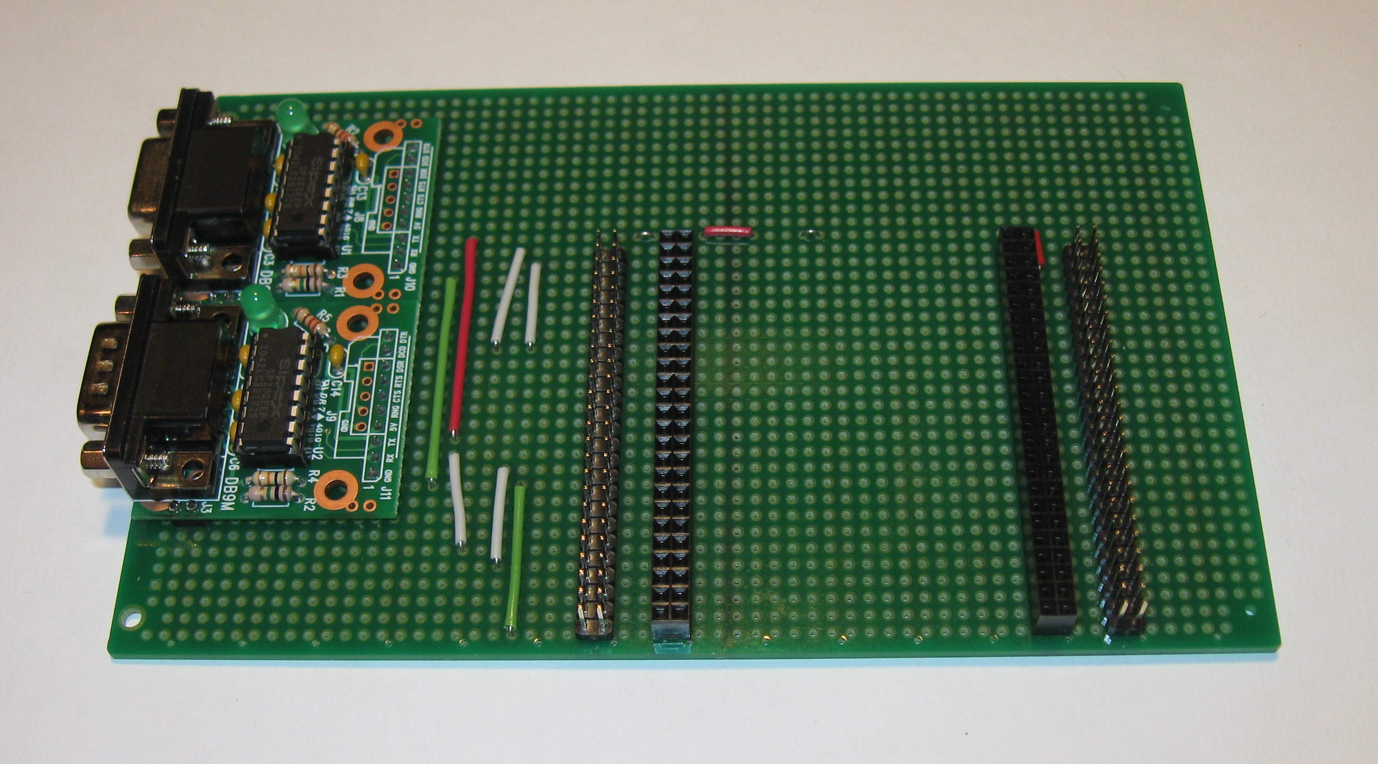
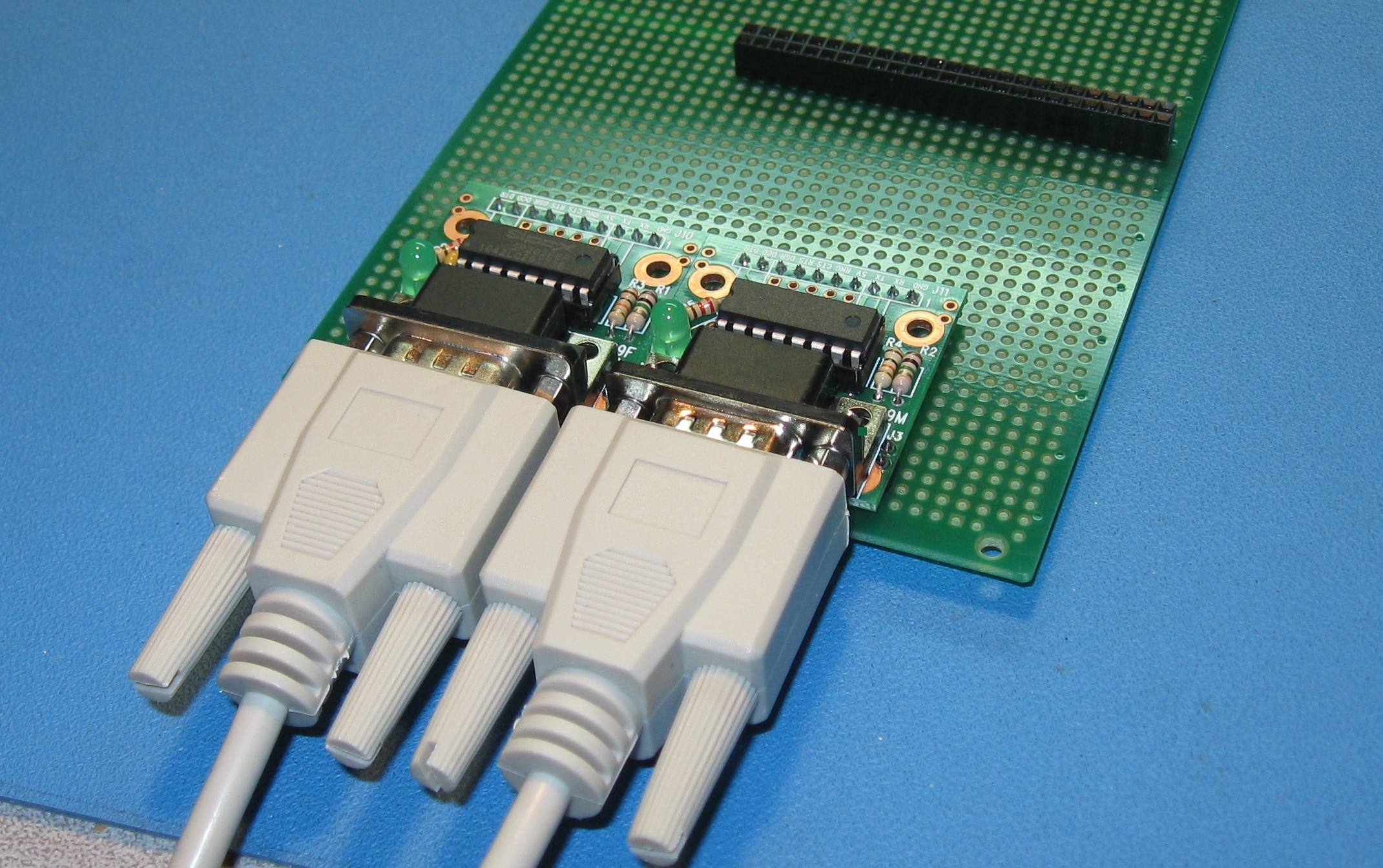
To add two 50-pin expansion headers, I used a BusBoard-3U prototyping board. The Discovery-F4 module plugs into two Tyco 50-pin sockets. The BusBoard zig-zag pattern connects two 50-pin male headers to the female sockets, pin-to-pin, without the need to add any wires. In the photo below you can see how the DIL header pins get connect 1 to 1, 2 to 2, etc. (click to enlarge).
The BusBoard pattern has two sets of conductors on each row, one carry the left pin signal and one carrying the right pin signal. These carry the Discovery-F4 signals past the male headers and allow other parts to connect to the signals, such as the serial port interfaces on this project. The two sets of conductors are made visually distinct by using wide pads for one and narrow pads for the other. A hole on side of the board marks the wide pads when viewing from the top side.
I cut all the tracks on the BusBoard in the middle to separate the left connector track from the right connector tracks. It is easiest to cut the narrow tracks. I used the soldering iron tip to heat up the cut track segments and push them off the board. They slide right off once heated enough. (Hint: Use an old tip to avoid removing the plating from your good soldering iron tip). The cut tracks have red marker on them in the following photo to make them more visible. Some tracks between the ComBoard pins and the DIL header needed to be cut as well.
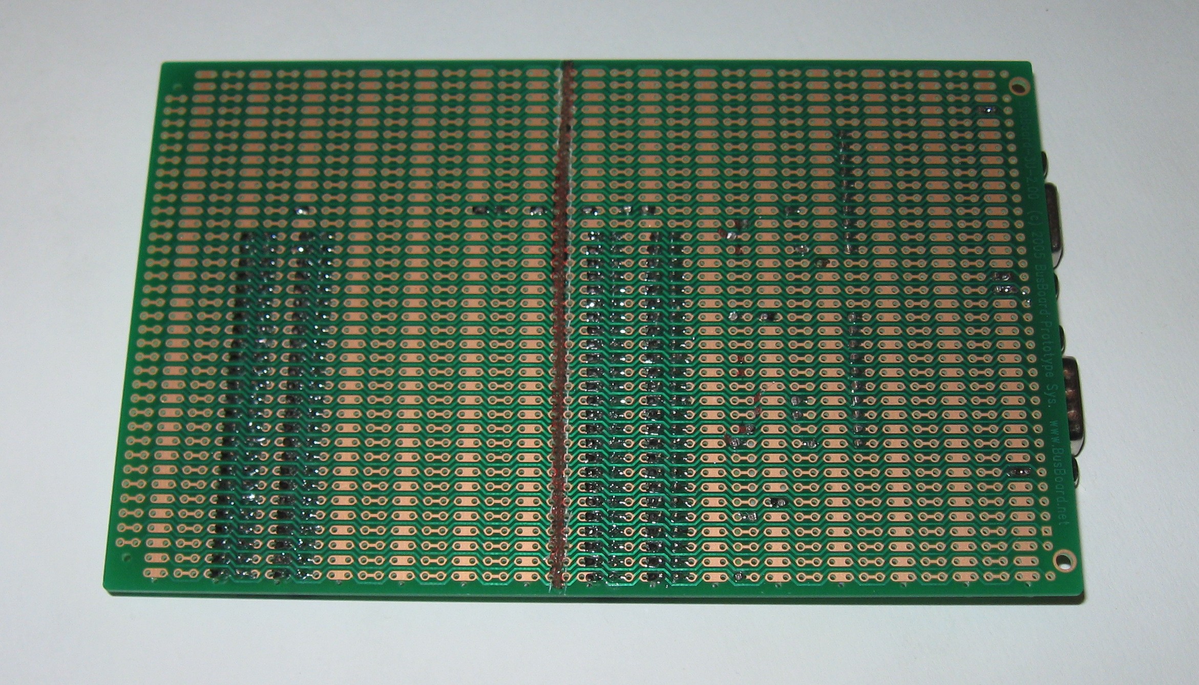
I had to add a red wire to carry the +5V power from the right side to the serial interface modules on the left. If I hadn’t cut all the tracks, this could have been avoided. Notice the two wire jumpers to the left and right of the red wire. These connect the narrow and wide tracks so it is carrying +5V power on both tracks in that row.
If you don’t need the 50-pin headers, a PR2H3U protoboard with 2-holes per strip may be preferable for a baseboard to provide simpler connections. The Discovery-F4 header pins would each be on separate pads, but the inner connections would need to be routed around the headers or wires added underneath.
RS232 Interfaces
I added two RS232 serial ports using ComBoard modules connecting to USART2 and USART3. I could have connected to USART1, but those pins are also used for the on-board USB-OTG. I did not want to use them to leave the option to use USB for future projects.
USART2 connects to a PC serial port so I used a ComBoard-232F module for a DCE port. USART3 uses a ComBoard-232M module for a DTE port, which will connect to a GPS module.
The following pins were used:
P1.13 PA3-USART2-RX
P1.14 PA2-USART2-TX
P1.40 PD8-USART3-TX
P1.41 PD9-USART3-RX
I decided to solder the ComBoard modules down to permanently attach them. I could have used a 10x1 SIL socket to make them changeable. There are 2-pin mounting holes (on the 0.1" grid) at the front of the module that allow it to be securely soldered down.
Breadboard Connections
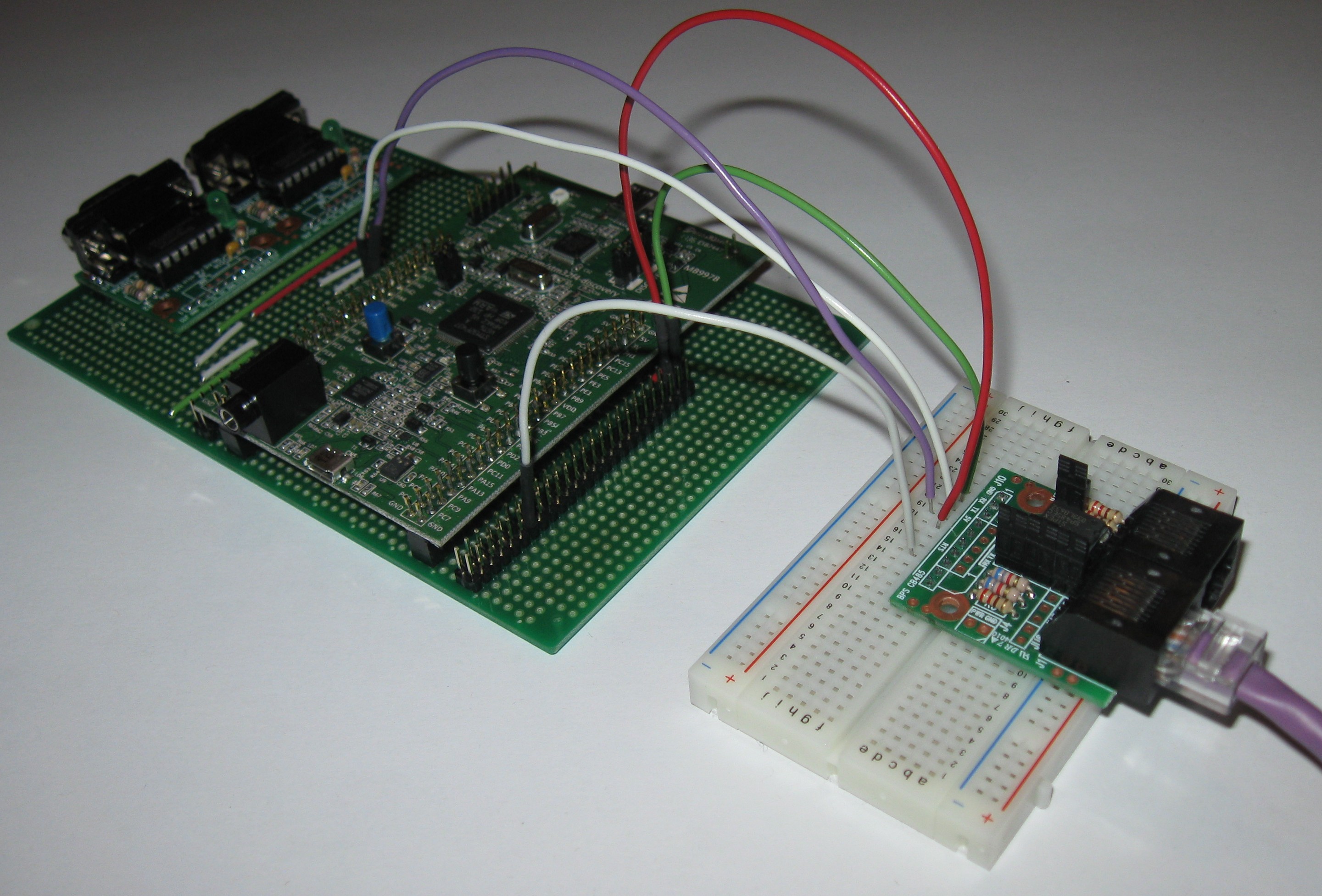
The 50 pin headers make it easy to connect to a breadboard for experimentation. Male-female jumper wires provide reliable connections that are easy to reconfigure.
This photo shows a RS485 interface module connected to UART4.
Parts
The following table has the manufacturer part numbers for the parts mentioned in this article.
BusBoard-3U
BusBoard BB3U Mouser Part#854-BB3U
ProtoBoard 2-Hole BusBoard
PR2H3U Mouser Part#854-PR2H3U
80-pin DIL Header Tyco
4-103186-0 Mouser Part#571-41031860
or Tyco 9-146256-0 Mouser Part#571-9-146256-0
(break 80 pin headers to the get the
needed 50 pin headers)
50-pin DIL Socket Tyco
2-534998-5 Mouser Part#571-25349985
or Tyco 7-534998-5 Mouser Part#571-7-534998-5
Discovery-F4 Module STM32F4DISCOVERY
Mouser #511-STM32F4DISCOVERY
Discovery-VL Module STM32VLDISCOVERY
Mouser #511-STM32VLDISCOVERY
Discovery-L Module
STM32L-DISCOVERY Mouser #511-STM32L-DISCOVERY
ComBoard CB232F
PCB-232F (bare PCB) Amazon.com/PCB-CB232F
ComBoard CB232M
PCB-232M (bare PCB) Amazon.com/PCB-CB232M
ComBoard CB485RJ
PCB-485 (bare PCB) Amazon.com/PCB-CB485
400point Breadboard BusBoard
BB400 Mouser Part # 854-BB400
I would appreciate any comments or suggestions you may have. Please send them to kornak.busboard@gmail.com (my Kornak Technologies/BusBoard Prototype Systems customer service email address).